Measuring the temperature with an Arduino and a thermistor
I’ve written a couple of previous posts about reading the temperature from and Arduino, storing it in the cloud-based time-series storage engine TempoDB, and visualising it. However, I haven’t explained in any detail how to use an Arduino to actually measure the temperature.
There are several methods available to you - including using digital sensor chips, some of which just record temperature, some which include other environmental data such as humidity, and thermocouples, which can be used to measure extreme temperatures. However, the simplest technique is to use a thermistor.
Thermistors
Thermistors are resistors which are sensitive to heat - i.e. their electrical resistance changes as the temperature changes. All resistors exhibit this property, but specialised thermistors are much more sensitive - making it easier to measure the temperature more accurately. Thermistors come in two varieties: positive temperature coefficient (PTC) and negative temperature coefficient (NTC). PTC thermistors are usually used as thermal cut-offs - the resistance increases as the temperature increases, which is a useful property in safety systems. NTC are the opposite - the resistance decreases as the temperature increases. This is the kind of thermistor we use in this project.
We approximate the relationship between temperature and resistance using the Steinhart-Hart equation:
where , & are Steinhart-Hart parameters, is resistance in Ohms and is temperature in Kelvin.
For NTC thermistors it’s easier to reformulate this equation as:
where is the reference temperature of the thermistor (usually 298.15K), is the value of the thermistor (available on the datasheet) and is the resistance at the reference temperature.
The thermistor we’re using in our circuit is a , at the reference temperature of 25°C (298.15K). It has a B-value of 3977 - which leaves just the resistance as an unknown.
Measuring resistance
We should all know how to do this. An arduino has multiple analogue input pins, each of which can sample the potential (or voltage). It digitises these values and you can read them back via the serial connection (see the Arduino section).
Since we can measure potential, we need to know how we can use this value to measure resistance. To do this we use a potential divider - one of the simplest constructs in the world of electronics, and something that everybody has learnt about at some point in school.
The important fact to recall is that in a series electronic circuit, the current is constant wherever it is measured, and the potential drops across resistive components. We apply Ohm’s law () to derive the following equation for the resistance of the 1st resistor:
We use a fixed resistor of 10k for , know the input voltage to be 5V and use the Arduino to measure the output voltage, so now we know the resistance of the thermistor, and hence the temperature.
Measuring voltage with the Arduino
Arduinos have some analogue to digital converter (ADC) pins. These measure the potential of a given pin (with reference to the board’s ground) - in layman’s terms - the voltage at a given point of a circuit. This is exactly what we require for the potential divider we introduced above.
The image below shows the connections made on the arduino:
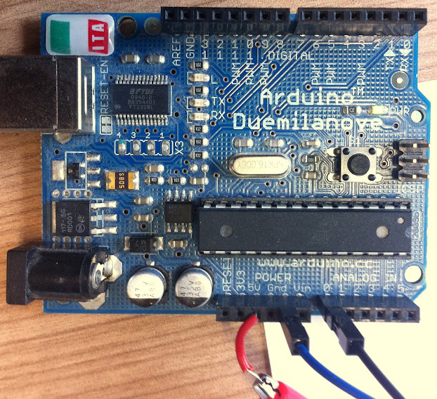
In order to read the value from the ADC pin 0 we write the following code to run on the Arduino:
This reads the value from the pin and then outputs the specified string to the serial port. Reading this in python was discussed in a previous post.
It is worth mentioning that the ADC is a 10-bit ADC. This means that there are 10 bits of resolution available in the measurement - i.e. it can be any value from 0 to 1023 (in decimal). The value sent along the serial connection is this integer value, which needs interpreting in order to translate it into a voltage.
ADCs read the potential in reference to 2 points provided - on the Arduino, the 5V power supply and ground. Therefore, a reading of 1023 in the ADC represents a potential of 5V - so converting from a reading to a potential is simple:
Putting it all together
So now we’ve built up the theory of thermistors, potential dividers and the Arduino’s ADCs to describe the technique used to determine the temperature. This is a pretty simple circuit - there’s a photo of the build here:
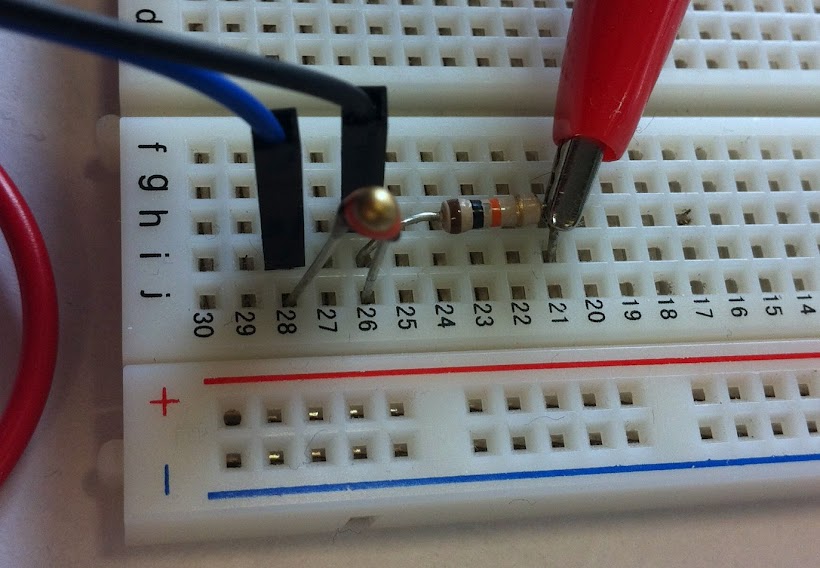
Have lots of fun, and feel free to grab any of the code I’ve put up on GitHub.
If you’ve enjoyed that post you should follow me on twitter @iwantmyrealname.
sx